01
Strength and stiffness margin
For the modelled 75 kN load, the report finds low stress and very small deformation, indicating substantial static strength and stiffness margins.
Project Case Study
Static strength assessment of a welded steel machine base frame under a 7,500 kg service load, with undamped modal characterisation using ANSYS Mechanical.
Service load
75,000 N
Steel yield strength
250 MPa
Peak von-Mises stress
13.87 MPa
1st natural frequency
401.14 Hz
Project summary
The finite element investigation assessed a welded steel machine base frame through linear static structural and undamped modal analyses. A 75,000 N downward service load was applied to the upper mounting rails with the supporting feet fixed.
Results include von-Mises stress, total deformation, elastic strain and the first six natural frequencies.
Analysis types
Linear static structural and undamped modal
Software
ANSYS Mechanical
Service load
75,000 N (7,500 kg), downward on the upper rails
Supports
Feet idealised as fully fixed
Primary outputs
Von-Mises stress, total deformation, elastic strain, first six natural frequencies
Reported values
Values are transcribed from the supplied 20-page base-frame analysis report. This page does not constitute an independent re-analysis or certification.
| Quantity | Reported result | Assessment |
|---|---|---|
| Maximum von-Mises stress | 13.87 MPa | FoS ≈ 18 against 250 MPa yield |
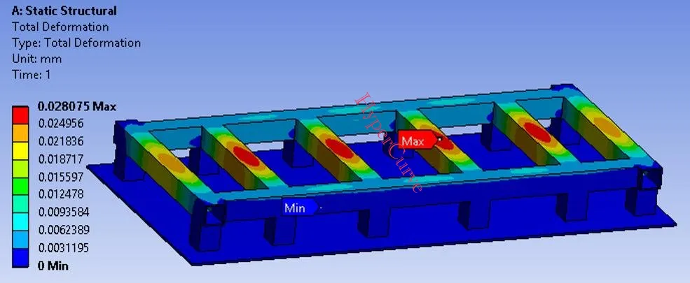
| Maximum total deformation | 0.0281 mm | Very low displacement |
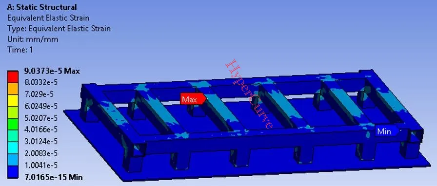
| Maximum equivalent elastic strain | 9.04 × 10⁻⁵ mm/mm | Linear-elastic response |
| 1st natural frequency | 401.14 Hz | Above typical machine excitation cited in report |
| 6th natural frequency | 432.87 Hz | Six modes within a narrow frequency band |
Model preparation
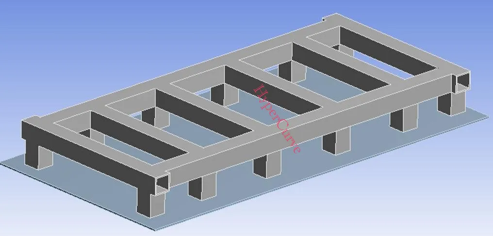
The frame is a welded ladder-type assembly comprising two longitudinal side rails, transverse cross-members and discrete supporting feet. The repeated open bays form the load-bearing deck, while the feet transfer reactions to the foundation.
The solid geometry was discretised using predominantly hexahedral and tetrahedral solid elements with quadratic displacement behaviour. Mesh refinement was applied around rail, cross-member and leg junctions where higher stress gradients were expected.
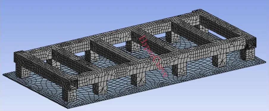

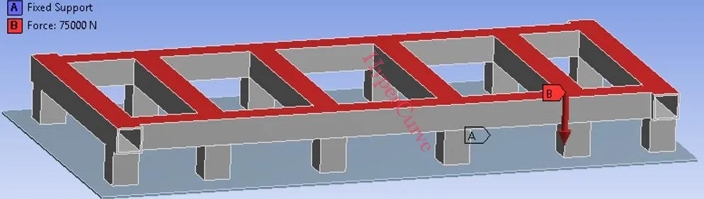
Analysis assumptions: structural steel treated as homogeneous, isotropic and linear-elastic; welded connections represented as fully bonded; load treated as quasi-static; support feet idealised as fully fixed.
Simulation results
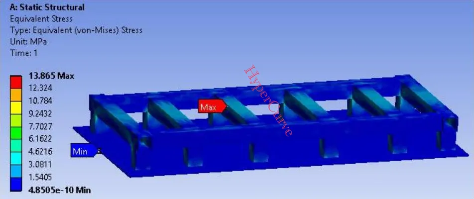
The peak stress of 13.87 MPa occurs near the loaded central cross-members. Against the stated 250 MPa structural-steel yield strength, the report calculates a factor of safety of approximately 18, indicating a substantial strength reserve for the modelled load case.
The maximum displacement of 0.0281 mm is reported at the mid-span of loaded rails between supporting legs, which the report interprets as very high global stiffness for the stated service load.
The peak strain of 9.04 × 10⁻⁵ mm/mm is consistent with the peak-stress region and remains within the linear-elastic range.
Dynamic behaviour
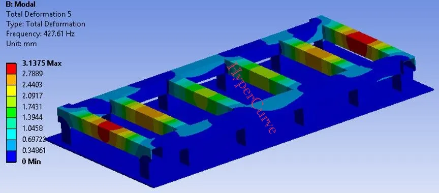
The undamped modal analysis extracted the first six natural frequencies using a direct solver. The corresponding mode shapes are described as predominantly rail bending across the unsupported spans, with activity shifting between bays.
| Mode | Frequency (Hz) | Dominant character (as reported) |
|---|---|---|
| 1 | 401.14 | End-bay rail bending |
| 2 | 406.99 | Central rail bending |
| 3 | 415.35 | Coupled bay bending |
| 4 | 420.68 | Alternating bay bending |
| 5 | 427.61 | Higher-order rail bending |
| 6 | 432.87 | Local rail / web mode |
Engineering interpretation
01
For the modelled 75 kN load, the report finds low stress and very small deformation, indicating substantial static strength and stiffness margins.
02
The first six natural frequencies range from 401.14 Hz to 432.87 Hz. The report considers these well separated from typical operating excitation; actual machine speed and excitation spectrum should be checked before final resonance sign-off.
03
The reported factor of safety suggests the frame may be a candidate for mass and cost optimisation, subject to verification of real loading, weld details, manufacturing tolerances and support conditions.
Next steps