Project Case Study

Masjid Ventilation CFD Analysis

A single-sided natural ventilation and thermal comfort study for a three-floor Masjid building, assessed at a peak occupancy of 300 people.

Natural VentilationAirflow SimulationThermal Comfort300-Person Occupancy

Building

Three floors

Peak occupancy

300 people

Ventilation

Single-sided

Time snapshots

30s & 130s

Project summary

Project at a Glance

This CFD study compared three airflow configurations while considering the existing building's architectural features.

The comparison focused on temperature and velocity patterns at 30 seconds and 130 seconds.

Building

Existing three-floor Masjid

Peak occupancy

300 people considered

Configurations

Straight inlet, 45° inlet, straight inlet with ceiling fan

Evaluation planes

Ceiling level, floor level and cross-section

Comparison times

30 seconds and 130 seconds

01 / Context

Project Overview

HyperCurve Solutions Private Limited carried out a Computational Fluid Dynamics (CFD) study of an existing three-floor Masjid building to evaluate ventilation and thermal comfort under single-sided natural ventilation. The assessment considered peak occupancy of 300 people while retaining the existing wall craftsmanship and architectural features.

02 / Scope

Project Objectives

The study examined how the orientation of incoming air affects ventilation through the main hall. It compared straight airflow, airflow entering at 45 degrees, and straight airflow with a ceiling fan to understand temperature development and air movement in the occupied space.

Model preparation

CAD Model and Airflow Inlet Design

The existing building layout was represented in CAD, including supply/return grilles, ducting and damper locations. The inlet design review also covered façade openings and door/window details used to establish the airflow entry configuration.

CAD layout showing supply and return grilles, ducting and damper locations
CAD layout — supply/return grilles, ducting and damper locations
Airflow inlet design showing façade openings and door and window details
Airflow inlet design — façade openings and door/window details

Simulation setup

Meshing and Evaluation Planes

A volume mesh was generated for the building domain. Results were examined on Plane 1 at ceiling level, Plane 2 at floor level, and Plane 3 at a cross-section through the building.

CFD volume mesh of the building domain
Volume mesh of the building domain
CFD evaluation planes at ceiling level, floor level and cross-section
Evaluation planes — ceiling level, floor level and cross-section

Simulation results

Air Temperature Results — Plane 1

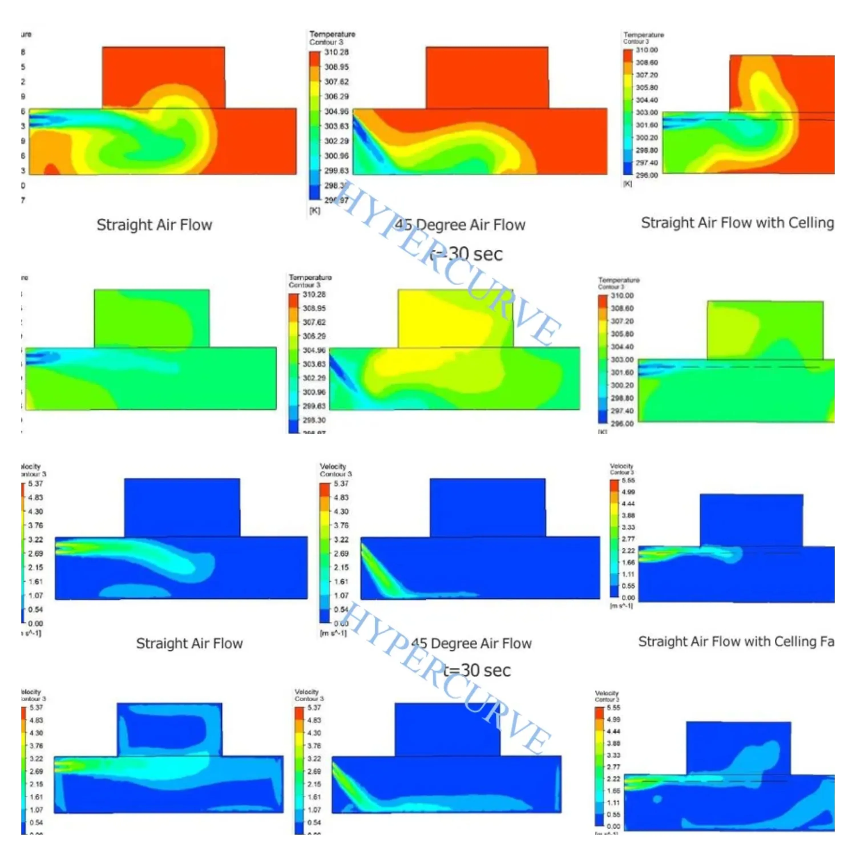
The reported contours compare straight airflow, 45-degree airflow and straight airflow with a ceiling fan at 30 seconds and 130 seconds.

Air temperature CFD contour results at Plane 1
Air temperature results — Plane 1

Straight airflow

The described areas remain warm, at approximately 308 K or higher, when straight airflow is used without a ceiling fan.

Ceiling-fan-assisted airflow

Adding a ceiling fan visibly improves mixing and lowers occupied-zone temperature over time.

45-degree inlet

The 45-degree inlet case performs worse than the straight-flow case in the reported comparison.

Air movement

Air Velocity Results — Plane 1

Velocity contours show how inlet direction affects the penetration of incoming air into the occupied zone.

Air velocity CFD contour results at Plane 1
Air velocity results — Plane 1

Noticeable air movement is visible in the occupied zone for straight airflow and for straight airflow combined with a ceiling fan.

In the 45-degree case, minimal velocity reaches the room interior. This indicates that inlet direction is important to how effectively incoming air penetrates the space.

Design implication: evaluate the inlet direction together with air circulation in the occupied zone, not only at the opening.

Sectional review

Cross-Section Results — Plane 3

Cross-section temperature and velocity results reinforce the trends observed on Plane 1, showing how airflow and cooling move through the occupied volume.

Cross-section CFD temperature and velocity results at Plane 3
Cross-section results — temperature and velocity, Plane 3

What the section reveals

Airflow penetration through the hall

Straight airflow, with or without a ceiling fan, drives air movement and cooling deeper into the hall than the 45-degree airflow case.

Engineering interpretation

Key Findings and Engineering Recommendations

The findings below reflect the configurations and conditions described in this case study; final design decisions should be validated against project-specific site conditions and applicable requirements.

01

Align the inlet

Single-sided ventilation performs best in this comparison when incoming air is aligned straight with the inlet (0°).

02

Review off-angle flow

The assessed 45° airflow configuration under-performs and sends less air movement into the room interior.

03

Improve air mixing

A ceiling fan improves air mixing and reduces occupied-zone temperature compared with straight airflow alone.

For the assessed peak occupancy of 300 people, the study recommends prioritising an aligned inlet orientation and including ceiling fans to support thermal comfort.

Project outputs

Project Deliverables

The assessment produced geometry, mesh and visual result outputs to support the ventilation comparison.

  • CAD layout and airflow inlet design review
  • Building-domain volume mesh
  • Defined evaluation planes at ceiling level, floor level and cross-section
  • Temperature contour comparisons for three airflow configurations
  • Velocity contour comparisons for the same configurations
  • Cross-section results and engineering recommendations