Project Case Study

Car Parking Basement — Fire & Smoke CFD Analysis

Jet-fan ventilation, air velocity and smoke (CO₂) evacuation study for Basement 2 (T10), covering Zone 1 and Zone 2.

Fire & Smoke CFDJet-Fan VentilationCO₂ MovementBasement 2 · T10

Jet fans

10 × GJX-36

Exhaust shafts

2

Fan airflow capacity

3,620–4,070 CFM

Comparison times

0 s / 60 s

Project summary

Project at a Glance

This study evaluated jet-fan ventilation performance during a fire scenario by tracking air velocity and CO₂ concentration over time to review movement towards the exhaust paths.

Results include velocity contours at the jet-fan mid-plane and CO₂ concentration contours at 0 seconds and 60 seconds.

Study area

Basement 2 (T10), Zone 1 and Zone 2

Jet fans

10

Exhaust shafts

2

Fan model

GJX-36, 355 mm diameter

Airflow capacity

3,620–4,070 CFM

Ceiling clearance

500–700 mm

Comparison times

0 seconds and 60 seconds

01 / Context

Project Overview

HyperCurve Solutions Private Limited carried out a Computational Fluid Dynamics (CFD) study of Basement 2 (T10) in a car parking facility to evaluate jet-fan ventilation performance during a fire scenario. The simulation tracked air velocity development and smoke represented by CO₂ concentration over time, with the aim of assessing how effectively hot gases are directed from the parking zones towards the exhaust paths.
02 / Scope

Project Objectives

The study examined the basement layout across Zone 1 and Zone 2, the placement of jet fans and exhaust shafts, airflow development after fan activation, and the movement of CO₂ concentration contours over the reported time interval. The report presents the results as an initial assessment supporting a more detailed CFD stage for design validation and code-compliance reporting.

Model preparation

Basement Layout and Jet-Fan Specification

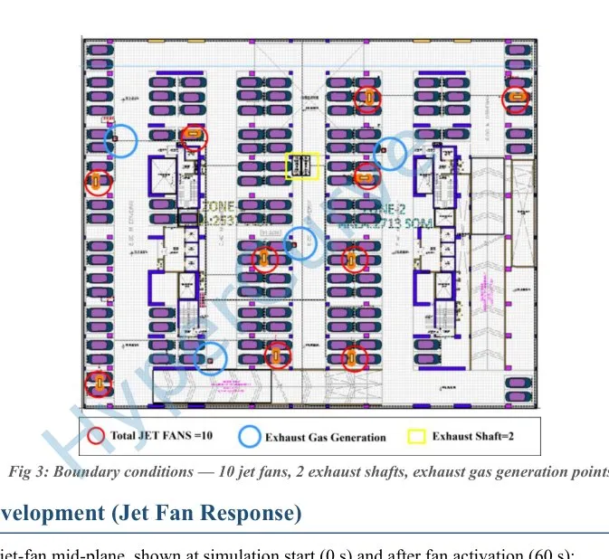
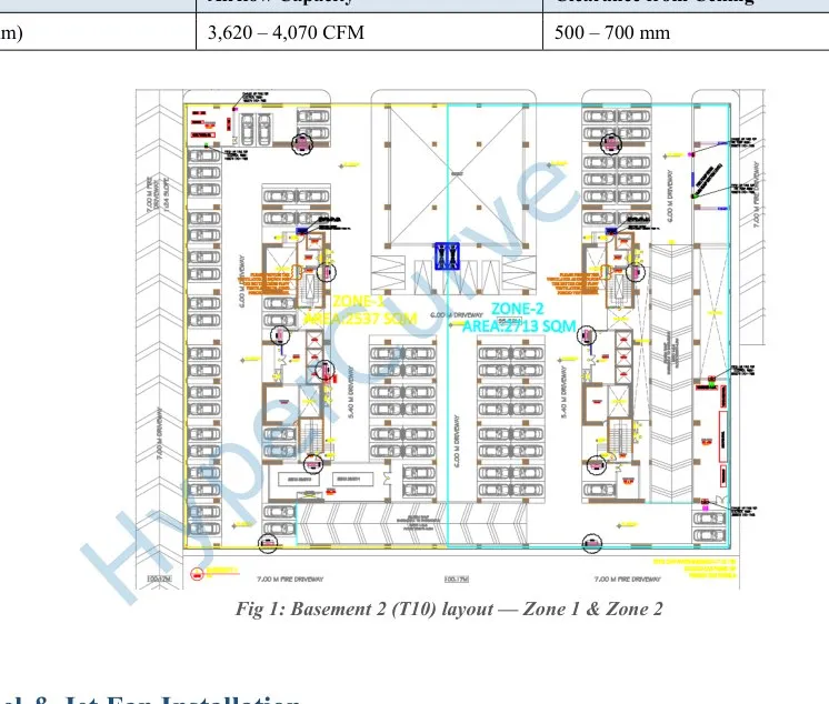
The report identifies the study area as Basement 2 (T10), comprising Zone 1 and Zone 2. The boundary-condition layout includes 10 jet fans, 2 exhaust shafts and exhaust-gas generation points.

Basement 2 T10 layout showing Zone 1 and Zone 2
Basement 2 (T10) layout showing Zone 1 and Zone 2

Fan model

GJX-36 with a diameter of 355 mm and a stated airflow capacity of 3,620–4,070 CFM.

Ceiling clearance

The specified clearance from the ceiling is 500–700 mm.

Simulation setup

CFD Model and Boundary Conditions

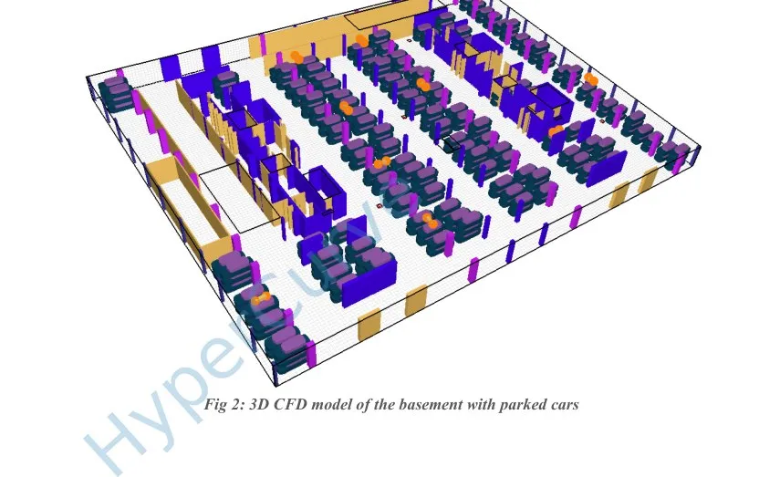
A three-dimensional CFD model represents the basement with parked vehicles. The boundary-condition plan marks the jet fans, exhaust shafts and exhaust-gas generation points. These model features establish the configuration used to examine directional airflow through the parking driveways and smoke movement towards the exhaust routes.

Three-dimensional CFD model of the basement with parked cars
Boundary conditions showing 10 jet fans, 2 exhaust shafts and exhaust gas generation points
Boundary conditions — 10 jet fans, 2 exhaust shafts and exhaust-gas generation points

Jet fans

10

Exhaust shafts

2

Zones

Zone 1 and Zone 2

Simulation results

Air Velocity Development

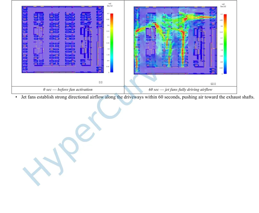
Velocity contours at the jet-fan mid-plane compare the simulation at 0 seconds, before fan activation, with the result at 60 seconds after activation.

Air velocity contours at 0 seconds before fan activation and 60 seconds after fan activation
Air velocity contours at 0 seconds (before fan activation) and 60 seconds (after fan activation)

At 0 seconds

The initial condition before the jet fans are activated.

At 60 seconds

The report states that the jet fans establish strong directional airflow along the driveways within 60 seconds, pushing air towards the exhaust shafts.

Smoke movement

Smoke (CO₂) Evacuation

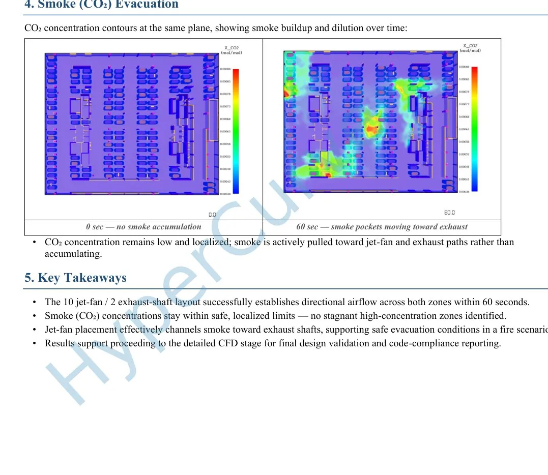
CO₂ concentration contours compare the initial condition at 0 seconds with the distribution at 60 seconds.

CO2 concentration contours at 0 seconds and 60 seconds showing smoke movement toward exhaust paths
CO₂ concentration contours at 0 seconds and 60 seconds showing smoke movement toward exhaust paths

The report describes the concentrations as low and localised, with smoke pockets moving towards the jet-fan and exhaust paths rather than accumulating in stagnant high-concentration zones.

Review the 0-second and 60-second contours together with the velocity results to follow how smoke is channelled towards the exhaust shafts.

Engineering interpretation

Key Findings and Design Implications

These findings summarise the supplied report's stated simulation results. They are not an independent validation of measured site performance.

01

Directional airflow

The 10 jet-fan and 2 exhaust-shaft arrangement establishes strong directional airflow along the driveways across both zones within 60 seconds.

02

No stagnant CO₂ zones

The presented CO₂ contours are low and localised, with no stagnant high-concentration zones reported. Smoke pockets move towards the jet-fan and exhaust paths.

03

Detailed CFD recommended

The report presents an initial assessment and recommends proceeding to a detailed CFD stage for final design validation and code-compliance reporting.

The report concludes that the jet-fan placement channels smoke towards the exhaust shafts and recommends a detailed CFD stage for final design validation and code-compliance reporting.

Project outputs

Project Deliverables

The study provides model views and visual result outputs to review airflow direction and smoke movement in the parking basement.

  • Basement 2 (T10) layout and zone review
  • Three-dimensional CFD model of the basement and parked vehicles
  • Jet-fan, exhaust-shaft and exhaust-gas generation boundary-condition layout
  • Air velocity contour comparison before and after fan activation
  • CO₂ concentration contour comparison at 0 seconds and 60 seconds
  • Summary of airflow direction and smoke movement observations