Project Case Study

DG Set Test Room CFD Analysis

An airflow and thermal assessment of a diesel generator test room, examining fresh-air delivery, radiator cooling, hot-air exhaust and potential recirculation around the genset.

Ventilation CFDThermal AnalysisVelocity StreamlinesRecirculation Assessment

Equipment

DG test room

Mesh nodes

686,239

Mesh elements

3,747,403

Assessment

Airflow & thermal

Project summary

Project at a Glance

The study assessed whether fresh air reaches the radiator and engine as intended and whether heated air is exhausted without harmful recirculation onto the genset.

Results include airflow streamlines, 3D velocity and temperature renderings, and horizontal-plane contours through the DG set.

Equipment

Diesel generator (DG) set test room

Mesh type

Tetrahedral room and genset mesh

Mesh nodes

686,239

Mesh elements

3,747,403

Key sources

Engine heat flux and radiator fan

Evaluation outputs

Velocity streamlines, 3D volume results and horizontal-plane contours

01 / Context

Project Overview

HyperCurve Solutions Private Limited carried out a Computational Fluid Dynamics (CFD) study of a diesel generator (DG) set test room to assess ventilation airflow and thermal performance. The analysis examined whether fresh air reaches the radiator and engine as intended, and whether heated air is exhausted without harmful recirculation back onto the genset.
02 / Scope

Project Objectives

The study focused on airflow through the test room, cooling-air delivery across the radiator and engine, exhaust flow, local recirculation and temperature distribution around the DG set. Velocity streamlines, volume renderings and representative plane sections were used to review the ventilation arrangement.

Model preparation

Test Room Setup and Ventilation Layout

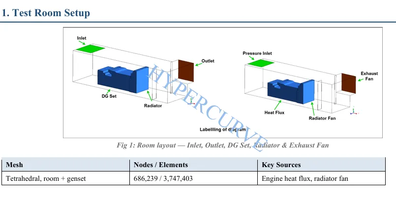
The model includes the room, DG set, radiator, inlet, outlet and exhaust fan. Engine heat flux and the radiator fan were identified as key sources for the airflow and thermal assessment.

Test room layout showing inlet, outlet, DG set, radiator and exhaust fan
Test room layout — inlet, outlet, DG set, radiator and exhaust fan

Simulation setup

Meshing and Model Detail

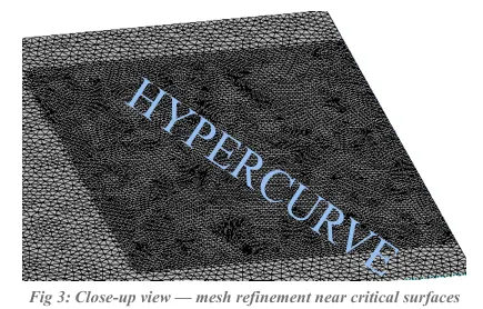
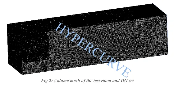
A tetrahedral mesh was generated for the room and genset, with local refinement around the DG set, radiator and inlet/outlet openings to better capture airflow near critical surfaces.

Volume mesh of the test room and DG set
Close-up mesh refinement near critical surfaces
Local mesh refinement near critical surfaces

Mesh nodes

686,239

Mesh elements

3,747,403

Simulation results

Airflow and Velocity Results

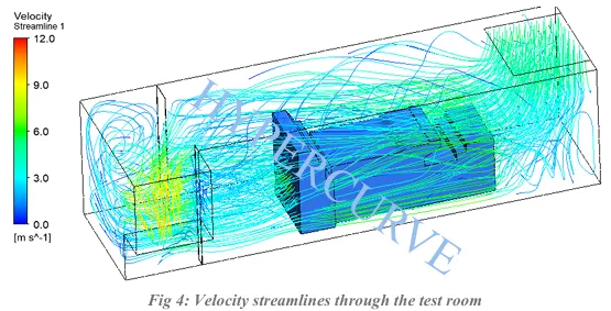
Velocity streamlines and the three-dimensional velocity rendering show fresh air entering the room and moving through the radiator toward the exhaust. The report describes the resulting cooling airflow as adequate for the assessed setup.

Velocity streamlines through the DG test room

Fresh-air delivery

The reported flow path brings incoming air through the radiator before it moves toward the exhaust.

Recirculation assessment

Local recirculation is visible near walls and corners, but the report does not identify harmful backflow onto the genset.

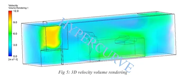
Velocity volume

The 3D velocity result provides another view of the airflow paths through the equipment room.

Three-dimensional velocity volume rendering

Thermal behaviour

Temperature Results

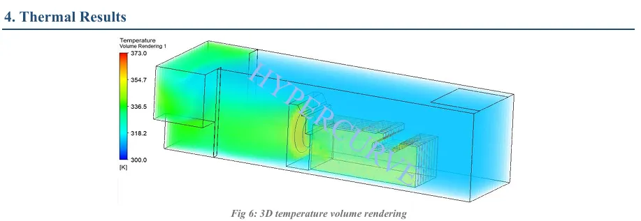
The temperature volume rendering shows hotter air around the engine and radiator-fan discharge, with cooling as air travels toward the outlet. The report does not identify abnormal hot-spot build-up.

Three-dimensional temperature volume rendering of the DG test room
Three-dimensional temperature volume rendering

The main room is reported to have a broadly uniform temperature distribution.

A localised temperature rise appears downstream of the radiator fan, consistent with the expected hot-air discharge path described in the report.

Thermal interpretation: review the full room temperature pattern together with the radiator discharge and exhaust airflow path.

Sectional review

Representative Horizontal-Plane Results

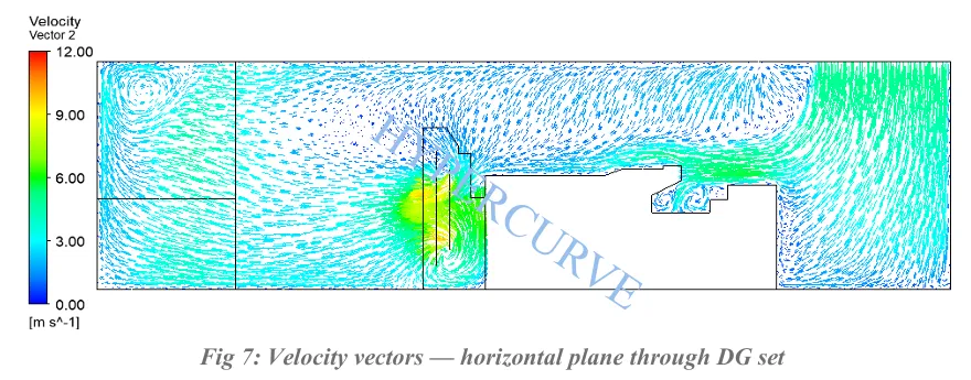
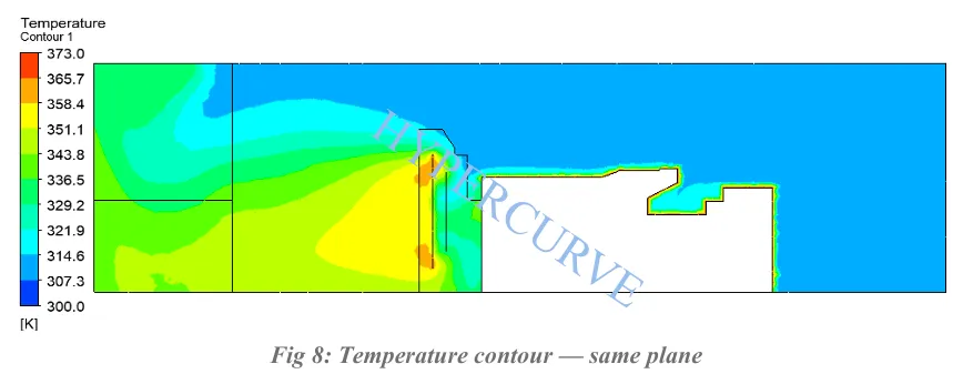
Horizontal-plane velocity vectors and temperature contours provide a focused view of airflow and thermal behaviour through the DG set.

Velocity vectors on a horizontal plane through the DG set
Velocity vectors on the horizontal plane
Temperature contour on the horizontal plane through the DG set
Temperature contour on the horizontal plane

The report notes localised recirculation near the inlet corner, but it does not cause backflow onto the genset. The main room remains broadly uniform in temperature, with a localised rise downstream of the radiator fan.

Engineering interpretation

Key Findings and Engineering Conclusion

These findings summarise the supplied report's stated simulation results. They are not an independent validation of measured site performance.

01

Adequate cooling airflow

The reported inlet, radiator and exhaust-fan arrangement provides airflow across the DG set and supports the intended cooling path.

02

No harmful genset backflow

Local recirculation near walls, corners and the inlet area is reported, but it does not return hot air onto the genset.

03

Broadly uniform room temperature

The main room shows a broadly uniform temperature distribution, with a localised rise downstream of the radiator fan as expected.

Based on the reported airflow and thermal analysis, the original report states that no design change was required for the intended DG capacity.

Project outputs

Project Deliverables

The study provides geometry, mesh and visual result outputs to review ventilation and thermal performance around the DG set.

  • Test room layout and ventilation arrangement review
  • Tetrahedral volume mesh and local mesh-refinement views
  • Velocity streamlines through the DG test room
  • Three-dimensional velocity volume rendering
  • Three-dimensional temperature volume rendering
  • Horizontal-plane velocity vectors and temperature contours
  • Summary of cooling airflow, recirculation and thermal behaviour

Technical basis: the supplied DG Set Test Room CFD report. This page summarises the report's stated simulation results and does not claim independent validation or measured site performance.